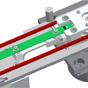
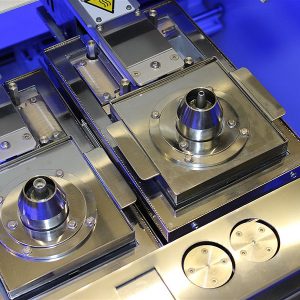
Description
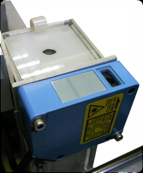
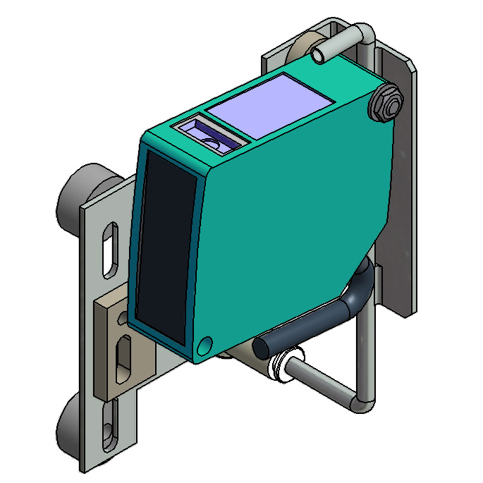
Because the board can distort more during the soldering process the height measurements can be programmed in sequence. The software automatically selects the nearest board warp measurement to make the correction.
Principle of Operation
For example a ‘Draw’ function, on a long connector, by taking a board warp reading at each end of the connector the software will automatically select the nearest warp point to the start and end of the ‘draw’ and will also calculate the vector between the two heights. The tip of the nozzle will follow the line between the two heights while the head moves between the start and end positions. Both board warp points must be programmed before the solder joints.
These board warp points will be used for all subsequent joints until a new board warp point is programmed.
It is possible to program all the board warp points at the start of the program so long as they are in a contiguous group. Subsequent solder joints will be assigned to the nearest board warp point in the group.


